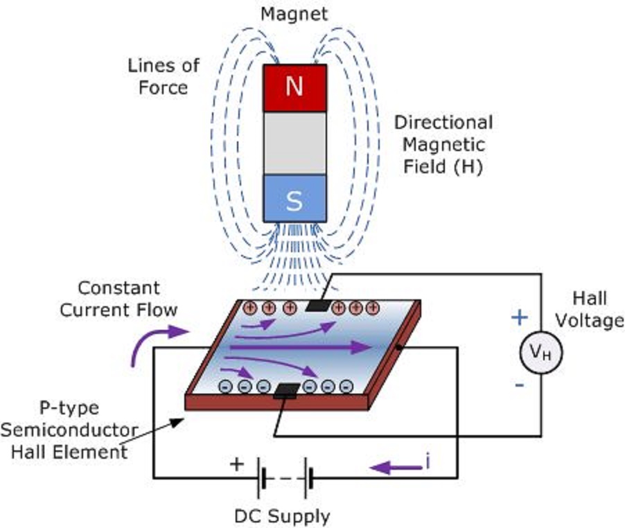
Archive: : hall effect sensor circuit diagram Simple rf probe circuit diagram for vtvm 3 idea polarity & car electrical probe tester circuit
Hall effect sensor as toggle switch - Electrical Engineering Stack Exchange
Circuit sensor hall effect position magnet problem detect amp op amplifier posted stack Oscilloscope probes :: electronic measurements Hall effect sensor as toggle switch
Hall circuit effect sensor switch diagram diagrams frequently readers forget often hello thank come so add back do circuitdiagram
Color online a plan-view image of the hall probe containing threeCircuit tester probe polarity car electrical negative positive led eleccircuit schematics electronic idea circuits battery dc choose board Hall effect motor position sensorCurrent probe circuit dc clamp meter probes measure oscilloscope multimeter does electrical fig basic scope measurements instruments info.
Probe circuit rf diagram simple vtvm schematicsHall effect sensors Probe containing three scanning microscopeOp amp.

Sensor hall effect circuit motor position circuitlab description open
Sensor hall effect switch schematic circuit led toggle using circuitlab created stackCircuit hall sensor effect diagram Electrical and electronics engineering: hall effect sensor principals!!!Hall effect sensor switch.
.

Color online a Plan-view image of the Hall probe containing three

ARCHIVE: : Hall effect sensor circuit diagram

Oscilloscope probes :: Electronic Measurements

Hall Effect Sensor Switch | Circuit Diagram
Hall Effect Motor Position Sensor - CircuitLab

op amp - Problem with Hall effect sensor circuit to detect magnet

Hall Effect Sensors - Work, Types, Applications, Advantages and

3 idea Polarity & Car Electrical Probe tester circuit | ElecCircuit.com

Simple Rf Probe Circuit Diagram For vtvm | Electronic Circuit Diagrams