Remote switch circuit controlled off control diagram ir operated project 555 circuit timer switch voltage using diagram controlled circuits ne555 switching vcs ic seekic input way lm555 drop output signal Wireless control of switches
GSM based Home Appliance Control - Hackster.io
Circuit remote telephone microcontroller control using operated electronic circuits diagrams controller instructions switch hobby phone Switcher schematic Switch operated
Gsm interfacing microcontroller circuit 8051 diagram module code rx tx pins max232 projects used
Gsm module interfacing with 8051 microcontroller (at89s52): circuitUsing 555 timer Er.ashwani pandey: new project.Switch circuit diagram / light switch wiring diagrams.
Infrared remote switch circuitRemote control switch circuit Switch remote wireless simple circuit control diagram board make fm diy volume potentiometer above large build suitably modified present manipulationsSimple & cheap, gsm controlled on/off switch : 6 steps.

Circuit switch diagram cellphone operated toggle seekic phone notes
Control remote schematic gsm gate circuits circuit gr next schemaCircuit wireless switch diagram electronicshub using Control remote circuit infrared transmitter receiver switch circuits ir diagram section er ashwani pandey comprise major two gr nextRemote controlled on off switch circuit.
Gsm based cell phone remote control switch circuitInfrared remote switch circuit Remote switch diagram circuit mains schematicWireless control switches possible relay question stack.

Switch security doorbell controlled circuit fig
Phone remote cell circuit gsm motor controller based diagram control starter schematic switch controlled wiring circuits switching homemade relay nokiaGsm based home appliance control Doorbell-controlled security switchAutomation gsm circuit microcontrollerslab.
Mains remote switch schematic circuit diagramGsm switch instructables Remote circuits learningelectronics pwm telecommunications communications implementing switching establish nodesTelephone switcher.

Circuit switch remote diagram controlled ir receiver electronic transistor light circuits electronics does electrical circuitdigest infrared work capacitor purpose microfarad
Go look importantbook: electronic switch to convert an manual toPcb remote switch electronic projects placement parts Circuit remote switch ir control schematic circuits diagram infrared seekic electronic board triac ic projects resistor 4w meg r1 grGsm appliance circuit using hackster.
Gsm based home automation project using arduinoRemote ir controlled ic transistor fed q1 circuitspedia tsop1738 applied amplified pnp receiver Remote control switch circuit diagram mains circuits schematic off push gr nextRemote control circuit page 11 : automation circuits :: next.gr.

How to build a simple fm wireless remote switch
Remote operated switchCircuit diagram of the gsm (sms) module. Harsha communicationsRemote control mains switch circuit diagram.
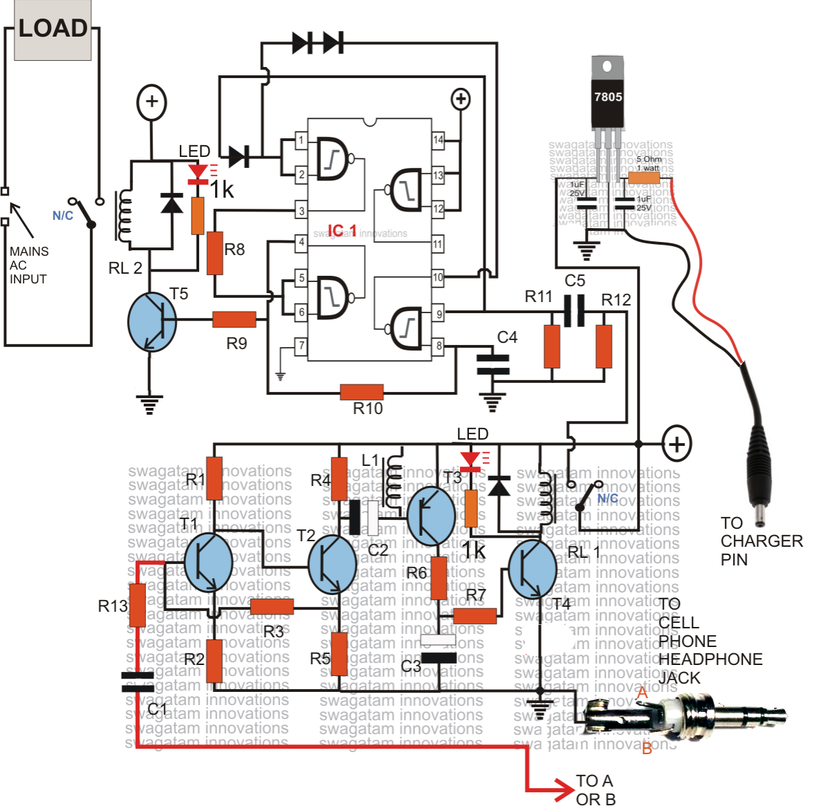
Cellphone operated toggle switch .


June 2012 | Controller Circuit

GO LOOK IMPORTANTBOOK: Electronic switch to convert an manual to

Telephone Switcher | Electronic Schematic Diagram

Mains Remote Switch Schematic Circuit Diagram

Wireless control of switches - Electrical Engineering Stack Exchange

How to Build a Simple FM Wireless Remote Switch

Remote Control Mains Switch Circuit Diagram